When capturing images with a camera, what actually happens in that the light rays that hit the sensor record the light color and intensity to form the image.
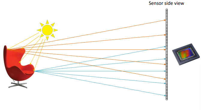
This way the same parts of the object get projected onto different parts of the sensor because of the physics of light and how it bounces off objects. We need to add a way to filter out most of the rays and only leave the ones that contain the correct amount of information. To such extent, we can use a wall which a small hole in it, which only lets through a small portion of the total rays of light.
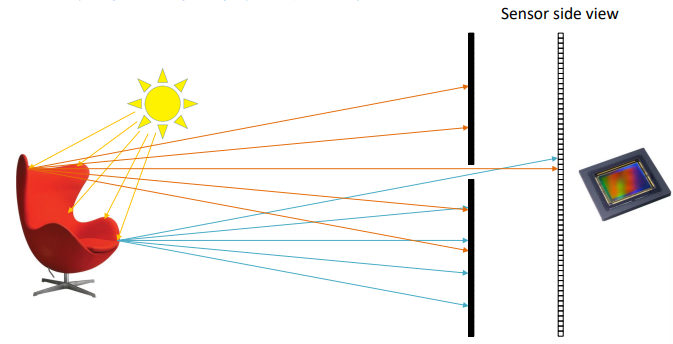
This model is called the pinhole camera model, in which the selection of the rays depends on the size of the hole. The ideal pinhole camera model is a dimensionless hole through which only one ray per point reaches the sensor. Obviously this model does not exist in real life.
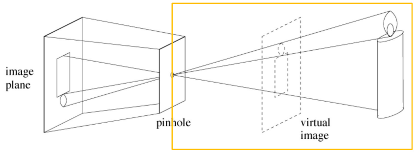
One problem with this is that the distance of different objects that perspectively overlap cannot be computed by only using the picture, as all objects get projected onto a virtual plane that contains a virtual image of the world. After passing through the pinhole, the image gets projected onto the sensor and has to be rotated.
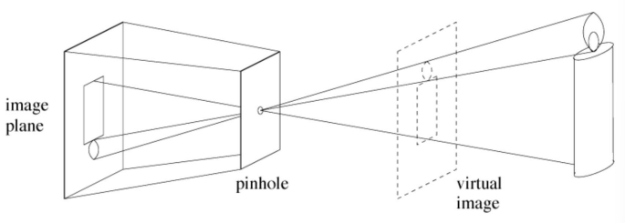
We can create a camera by using this model, in which the optical center is the location of the pinhole.
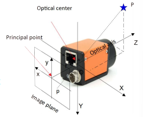
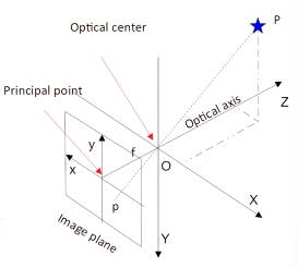
The principal point is the intersection of the image plane and the optical axis, while the focal length is the distance between the optical center and the image plane.
The orientation of the camera’s axis are found by using the right-hand rule.
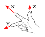
We now have two different reference systems: one that describes the camera, and one that describes the image plane.
Projective geometry
We need to find a way to describe the geometry of a camera in a quantitative way. Specifically, we need to find the relation between the reference system seen from the camera of the 3D world, and the 2D points represented on the image plane.
Let’s consider a point P and its projection p in 3D space.
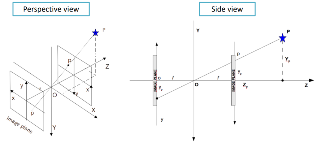
We can consider two image planes: the original one behind the optical center, and another one in front of it at the same distance. For simplicity purposes we can just consider the plane in the front.
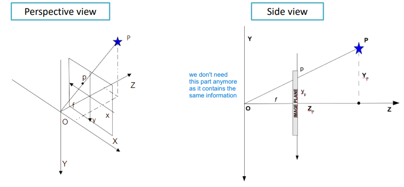
This way we are focusing on the virtual image instead of the real world objects.
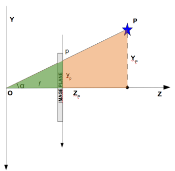
Given such geometry, different points can get projected onto the same image point, and because of the similarity between the green and red triangles, we can derive the equations below to compute the point’s projections onto the image plane.

\begin{aligned}
&x_p = f\,\dfrac{X_p}{Z_p}\\[10pt]

&y_p = f\,\dfrac{Y_p}{Z_p}\\[10pt]

&\tan(\alpha) = \dfrac{Y_p}{Z_p}
\end{aligned}
We can now rewrite such equations in matrix form using the homogeneous coordinates as
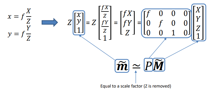
In which P is called the projection matrix.
In the case of f=1 we get the essential perspective projection:
P=
\begin{bmatrix}
1&0&0&0\\
0&1&0&0\\
0&0&1&0
\end{bmatrix}
=
[I \mid {\bf 0}]
One important consideration to make is that up until now we have considered images in the 3D spaces measured in meters and turned them into a virtual image using the same measuring unit. Images are made up of pixels though: how do we map meters to pixels?
Namely, how do we get from the (x, \, y) coordinates to the (u, \, v) ones that represent the pixels?
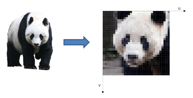
To start off, we can consider the coordinates of the principal point and set them to be (u_0, \, v_0), considering the origin of the pixels the top left corner of the image plane.

To convert meters to pixels we need to conversion factors that we can call k_u and k_v, obtained using the width w and height h of the pixels taken into account.
-k_u = \dfrac{1}{w}\\[10pt]

-k_v = \dfrac{1}{h}
Mapping between the two coordinate systems is therefore done by translating and scaling the points
u=u_0 + \dfrac{x_p}{w} = u_0 + k_u \, x_p=(\spades)\\[10pt]

v=v_0 + \dfrac{y_p}{k_v} = v_0 + k_v \, y_p = (\clubs)
By substituting such equations in the projection equation we can convert from meters to pixels and vice versa.
(\spades) = u_0 + \dfrac{f}{k_u} \, \dfrac{X_p}{Z_p} = u_0 + f_u \, \dfrac{X_p}{Z_p}\\[10pt]

(\clubs) = v_0 + \dfrac{f}{k_v} \, \dfrac{X_p}{Z_p} = v_0 + f_v \, \dfrac{X_p}{Z_p}
The projection matrix can now be expressed as
P =
\begin{bmatrix}
f_u & 0 & u_0 & 0\\
0 & f_v & v_0 & 0\\
0 & 0& 1 & 0
\end{bmatrix}
:= K[I \mid {\bf 0}]
In which K(\cdot) is the camera matrix.
The camera matrix itself if just this part K= \begin{bmatrix} f_u & 0 & u_0\\ 0 & f_v & v_0\\ 0 & 0& 1 \end{bmatrix} of the projection matrix. Such matrix depends on different Intrinsic parameters: k_u, \, k_v, \, u_0, \, v_0, \, f.
Moving from the image plane to the real camera plane
So far, we have mapped the world to the image plane and the image plane to pixels. However, a different reference frame can be defined on the world, and such transformation in called rototranslation.
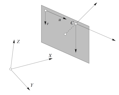
A rototranslation in homogeneous coordinates is expressed as
T=
\begin{bmatrix}
R & {\bf t}\\
{\bf 0} & 1
\end{bmatrix}
And the correspondence becomes
\widetilde{\bf m} \simeq P\,T\, \widetilde{\bf M}Where \widetilde{\bf m} is a vector and \widetilde{\bf M} is a matrix. In the rototranslation matrix T there are 6 parameters involved: 3 for translations and 3 for rotations. Such parameters are called extrinsic parameters.
The whole projection steps therefore become
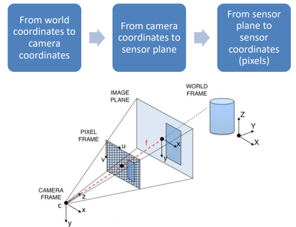
Inverse projection
Given the projected point \widetilde{\bf m}, can we get the original coordinates for the 3D point? In other words, can we invert from one system to the other? The short answer is no, as there are elements involved that are not invertible.
The only case in which we could do it is if we were to neglect the quantization effect, which projects different points in 3D space onto the pixel location when considering the 2D image plane.
Using lenses on cameras
Let’s introduce the thin lens model. When considering the pinhole model, a lens is added centered on the pinhole. The lens is supposed to be thin as in the ideal model, we can neglect its width. The lens deviates light and focuses rays on the sensor.
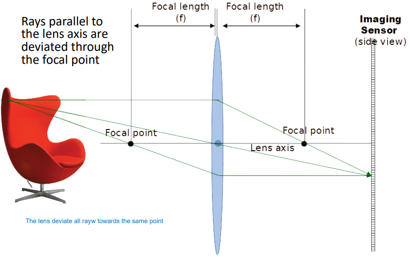
Calling d_0 the distance from the object to the lens and d_1 the distance from the lens to the sensor, we can derive the thin lens equation as
\dfrac{1}{d_0} + \dfrac{1}{d_1} = \dfrac{1}{f}Which describe the distances between the object and the lens, as well as between the lens and the image.
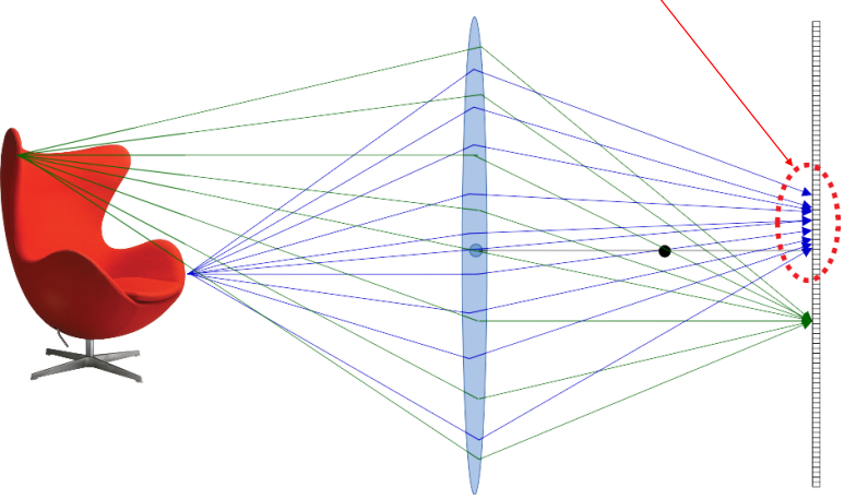
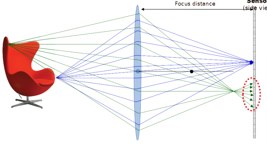
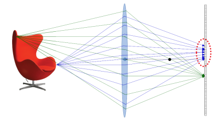
By using such lens all points at a given distance are in focus, while all other points at other distances are not in focus and generate a circle of confusion (in red).
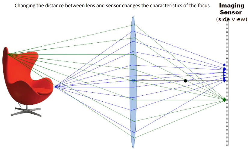
Changing the distance between the lens and sensor changes the characteristics of the focus.
To make sure that only a portion of the rays are considered and reduce the circle of confusion, we can add a barrier.
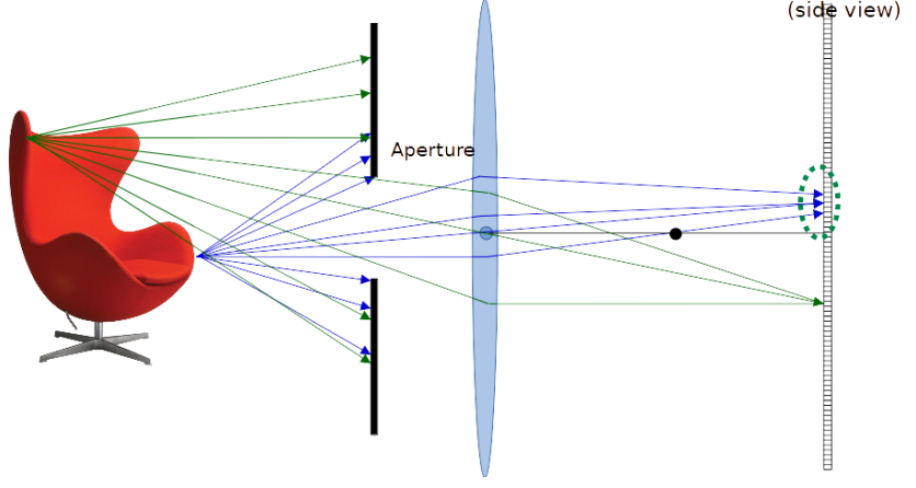
The focal length is represented by the distance at which parallel rays intersect, while the field of view is the angle perceived by the camera. The field of view depends on both the sensor size and the focal length. Its values is computed as
\varphi = \arctan\left(\dfrac{d}{2f}\right)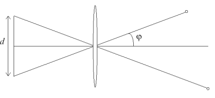
In the real world, the lenses we have just seen don’t really exist and the pictures get affected by additional side effects such as distortions and chromatic aberrations. Lens manufacturers try and keep under control distortions by using very complex arrays of lenses.

Regarding distortions, we can divide them into two categories:
- Radial: this kind of distortion measures how much something gets stretched or squeezed in a picture. It changes depending on how far that thing is from the middle of the picture.

It is divided into two different sub-categories:
- Pincushion distortion
- Barrel distortion
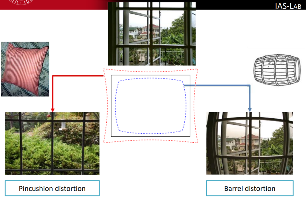
The radial distortion can be analyzed by means of distortion patterns but can be mathematically measured only if the lens’ structure is known in detail
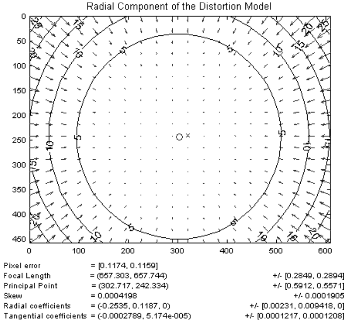
The camera models (even the ones used by OpenCV) use a polynomial approximation for the radial distortion. The coordinates (x_{\text{corr}}, \, y_{\text{corr}}) of the corrected point starting from the distorted point (x, \, y) are
x_{\text{corr}} = x \cdot \left(1 + k_1 r^2 + k_2 r^4 + k_3 r^6\right)\\

y_{\text{corr}} = y \cdot \left(1 + k_1 r^2 + k_2 r^4 + k_3 r^6\right)- Tangential: it happens when the lens and the camera’s sensor aren’t perfectly lined up. It makes things look a bit tilted or skewed, kind of like a “perspective” effect in the picture.
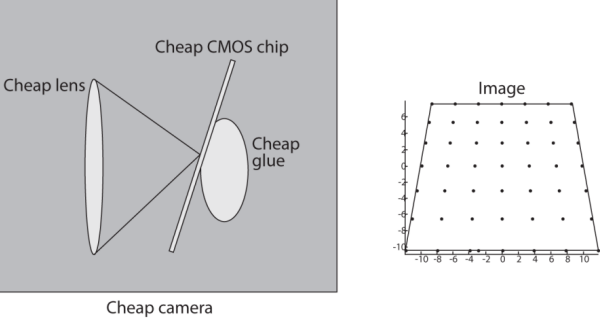
This kind of distortion is also modelled in terms of (x_{\text{corr}}, \, y_{\text{corr}}) as
x_{\text{corr}} = x + [2p_1 xy + p_2(r^2 + 2x^2)]\\

y_{\text{corr}} = y + [p_1(r^2 + 2y^2) + 2p_2 xy]
Chromatic aberration
Chromatic aberration affects how colors blend and how the lens focuses light, which causes colored fringes near the edges of the picture.
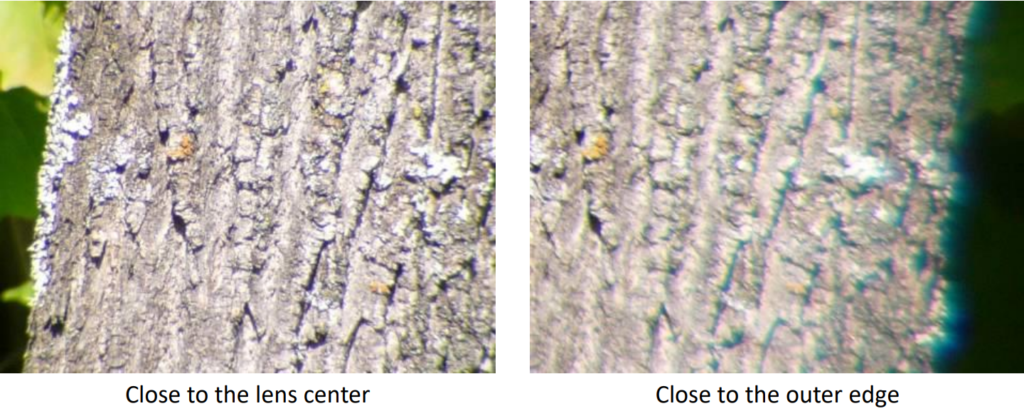
Real cameras
I will only summarize a few keypoints as the topics covered are well known in the context of photography.
When considering straight lines in the image plane, parallelism is lost.
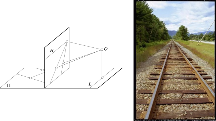
The true dimension of objects of different sizes at different distances are also lost.

Moreover, the effect of the pinhole is such that the image gets reversed when it is projected.
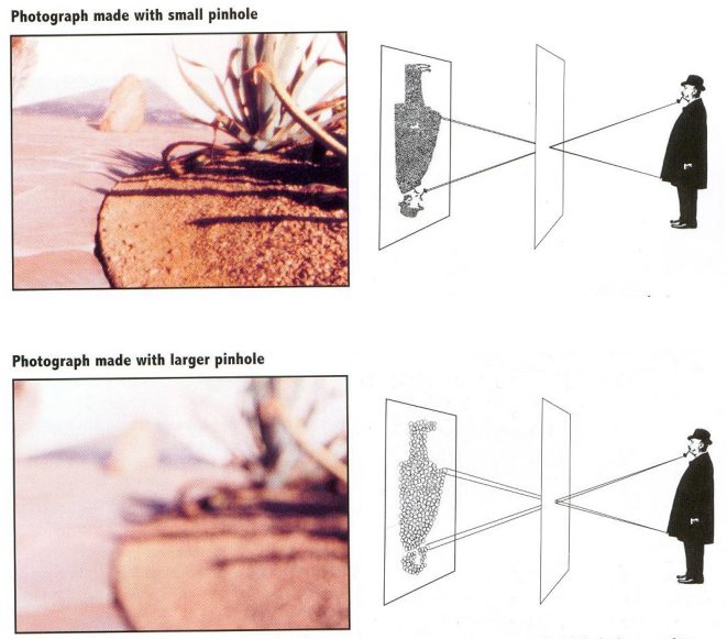
The pinhole is then substituted with a lens in real modern cameras.
Telephoto makes it easier to select background (a small change in viewpoint is a big change in background).
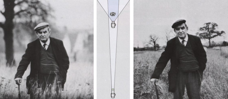
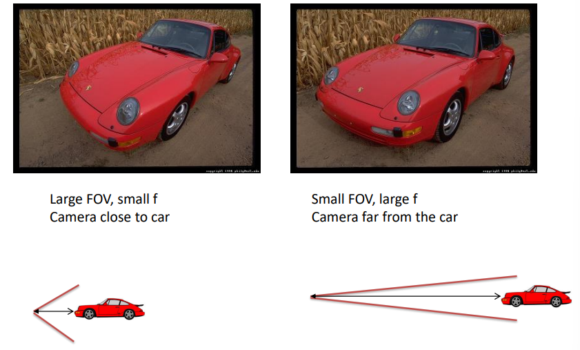
This kind of FOV can also be used to create the bokeh effect.

Sensors
A digital camera photons captured by the camera’s lens are transformed into electrons, marking the beginning of image formation. Two primary types of sensors dominate the digital camera landscape: CCD (Charge-Coupled Device) and CMOS (Complementary Metal-Oxide-Semiconductor). While CCD sensors excel in producing high-quality images with low noise levels, CMOS sensors offer advantages in power efficiency and faster readout speeds. This shift from film to sensor-based image capture not only enhances image quality but also paves the way for countless advancements in photography, from high-speed shooting to low-light performance, ultimately reshaping the way we capture and preserve moments.
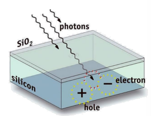

CCD and CMOS sensors do not inherently distinguish between wavelengths or photon energies; instead, they measure the total energy of incident light. Effectively serving as greyscale sensors, they lack inherent color sensing capabilities. However, both sensor types utilize different techniques to capture color information. Three-chip color systems split incident light into its constituent red, green, and blue components using filters and separate imagers for each color channel. Conversely, single-chip color systems employ a single imager with color filters to capture the entire spectrum of light. The degree to which each sensor type penetrates different wavelengths varies, influencing their respective abilities to capture and reproduce color accurately.
Physical pixel arrays
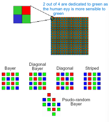
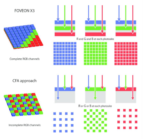
The Bayer Color Filter Array (CFA), also known as the Bayer mosaic, is a common arrangement of color filters used in digital camera sensors. Each pixel in a Bayer sensor is equipped with a single color filter, typically red, green, or blue, arranged in a specific pattern across the sensor surface. Due to this pattern and the presence of only one color filter per pixel, interpolation is required to reconstruct a full-color image from the sensor data. Interpolation involves estimating the missing color information by analyzing the values of neighboring pixels.
In contrast, direct image sensors, such as the Foveon sensor, do not utilize a color filter array. Instead, they employ layered sensor elements that directly measure the intensity of light at different wavelengths. This design eliminates the need for interpolation and minimizes information loss, resulting in potentially higher color fidelity and sharper images.
Exposure / aperture / shutter
A lens’ aperture represents the diameter of its opening. It is measured as a fraction of focal length (f-number). For example:
- If we consider a f-number of f/2.0 on a 50mm lens we get an aperture of 25mm;
- A f-number of f/2.0 on a 100mm lens would lead to an aperture of 50mm;
The exposure time represents the amount of time the shutter opens and closes in order to expose the sensor to light. It is expressed as a fraction of seconds, for example 1/60s or 1/125s.
Given a needed amount of light, the same exposure is obtained if we were to, at the same time, multiply that exposure value by 2 and divide the aperture area by 2 as well. The following parameters all yield the same amount of light, but generate different images nonetheless.

The different choices above can generate completely different images, though. Changing the shutter speed can in fact modify the amount of motion blur gotten in the final image, whilst changing the aperture would lead to different kinds of depth of field, for example the bokeh effect.
The different choices above can generate completely different images, though. Changing the shutter speed can in fact modify the amount of motion blur gotten in the final image, whilst changing the aperture would lead to different kinds of depth of field, for example the bokeh effect.
Moreover, having a longer exposure time implies having more light coming in, thus more motion blur, conversely, a shorter exposure time lets less light in and makes it possible to “freeze” motion.

Depth of Field
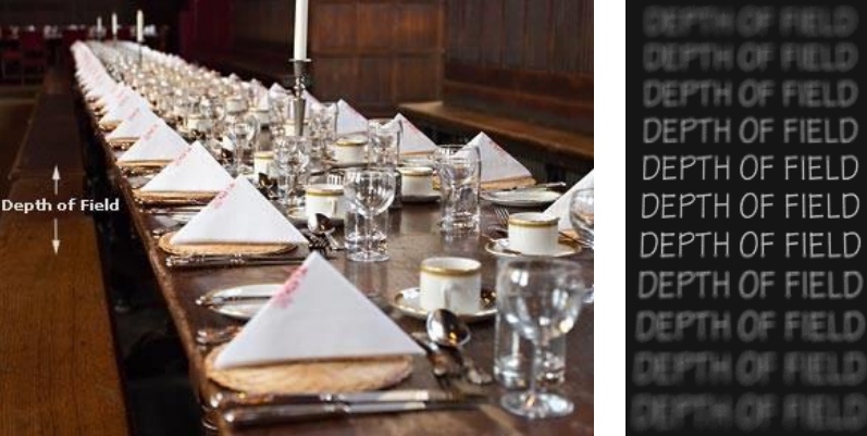
The aperture of a camera lens plays a crucial role in controlling the depth of field in a photograph. By adjusting the size of the aperture, photographers can manipulate the range in which objects appear sharply focused within an image. A smaller aperture, indicated by a higher f-stop number, increases the depth of field, meaning more of the scene—from foreground to background—will be in focus. Depth of field refers to the range of distances in front of and behind the focal point that appears acceptably sharp in an image. It’s essentially the depth within which the viewer perceives objects as being in focus, while areas outside this range are blurred to a degree considered acceptable, defined by the “circle of confusion.”

Calibrating a camera
Camera calibration is aimed at determining the intrinsic parameters of a camera system. Intrinsic calibration involves estimating parameters such as focal length, principal point, and lens distortion characteristics. This calibration is crucial for correcting image distortions and accurately measuring object dimensions or camera motion. In some cases, extrinsic parameters—such as camera position and orientation relative to a global coordinate system—are also determined, allowing for precise 3D reconstruction of scenes. While intrinsic calibration does not require a reference with a world coordinate system, it establishes a linkage between 3D objects and their projections in the image. Extrinsic calibration typically involves determining the camera’s position and orientation using dedicated techniques, often expressed as yaw, pitch, and roll angles or other terms such as pan and tilt.
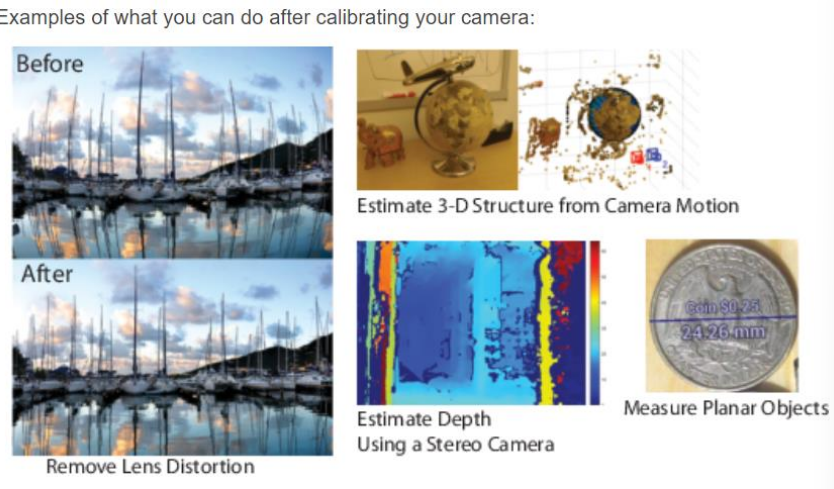
Camera calibration involves several methods, but generally follows a standard process. Initially, an object with a known shape and appearance, often a recognizable pattern like a checkerboard, is used. This pattern is placed in various positions and orientations relative to the camera, and multiple images of the pattern are captured. In each image, the positions of identifiable points, typically the corners of the pattern squares, are determined both in the pattern’s reference system and in the image’s reference system. These points serve as calibration data. The process involves collecting a sufficient number of images and their corresponding corner positions. Finally, the intrinsic calibration parameters of the camera, such as focal length and lens distortion, are estimated based on the collected data, often initialized to default values before refinement.
To help the calibration process the first step is to try and guess the parameters. The transformation from object to image plane can be represented by a homography, which is a projective transformation between two planes or, alternatively, a mapping between two planar projections of an image. A minimum of 2 views is needed to correctly calibrate the camera. In practise though, to get stable results 10 or more views are usually needed.

Image resampling
Image resampling is the process of changing an image resolution. Specifically, three different resampling strategies are used:
- Interpolation: to create a larger image
- Decimation: to create a smaller image
- Resampling to a different lattice (for example after a geometric transformation)
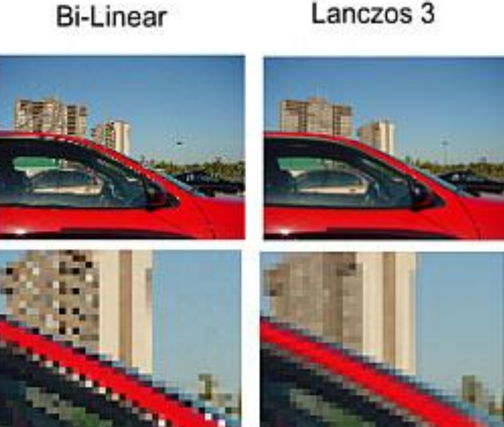
Note: the pixel colors can taken based on the closes pixels around the expanding ones in the case of interpolation. Another way to interpolate them is by using bilinear or bicubic interpolation. Bilinear interpolation works by averaging the nearest four known pixel values around the desired point to calculate the new pixel value, while the bicubic one involves a larger number of neighboring pixels—usually 16.

